


Ship to:
United States
Select the desired shipping method
- Shipping Company Estimated Delivery Time Shipping Cost


Highlights
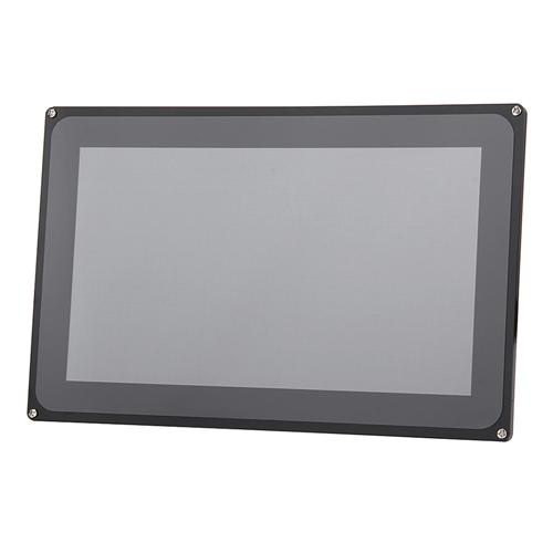
High Resolution Capacitive Touch Screen
- 10.1inch HDMI LCD consists of a 10.1inch Capacitive Touch LCD and an HDMI control board
- 1024*600 high resolution
- Capacitive touch control
Works with Raspberry Pi & monitor
- When works with Raspberry Pi, supports Raspbian, Ubuntu, Windows 10 IoT, single touch, and driver free
- When works as a computer monitor, supports Windows 10/8.1/8/7/XP, single touch, and driver free
- Supports BB Black, comes with Angstrom image
Video input interface & Multilanguage support
- Multi video input interfaces: HDMI, VGA, and AV(CVBS)
- Multi languages OSD menu, for power management, brightness/contrast adjustment, etc.
- Firmware is upgradable to support more new features (continually updated)
Specification
| General | |
|---|---|
| LCD Type | TFT |
| Interface | RGB/LVDS |
| Touch Controller | FT5406 |
| Touch Panel Type | Capacitive (5 multi-touch) |
| Backlight | LED |
| Display Size (mm) | 222.72(W)*125.28(H) |
| Dot Pitch (mm) | 0.2175(W)*0.2088(H) |
| Aspect Ratio | 16 : 9 |
| Resolution | 1024*3(RGB)*600 (Pixel) |
| Power Consumption | TBD |
| Backlight Current | TBD |
| Operating Temp. (ºC) | 0 ~ +70 |
| Development Resources | Wiki : www.waveshare.com/wiki/10inch_HDMI_LCD_(with_case) |
| Compatibility |
This item is compatible with the following products: MarsBoard RK3066 |
| Package Contents | |
| 10.1inch Capacitive Touch LCD (D) x 1 | |
| HDMI LCD control board x 1 | |
| HDMI cable x 1 | |
| USB type A plug to micro B plug cable x 1 | |
| 40-pin FFC x 1 | |
| Case for 10.1inch LCD × 1 | |
| Screws pack x 1 | |
| Bottom holder x 2 | |
| Power adapter 12V/1A × 1 | |
| DVD × 1 | |
RGB Interface Definition
| PIN NO. | SYMBOL | DESCRIPTION | Type | FUNCTION |
|---|---|---|---|---|
| 1 | BL_VDD | Power positive | Power | Backlight power, connects to 5V power supply |
| 2 | BL_VDD | |||
| 3 | GND | Ground | GND | |
| 4 | VDD | Power positive | Connects to 3.3V power supply | |
| 5 | R0 | Data pin | Input | Red data |
| 6 | R1 | |||
| 7 | R2 | |||
| 8 | R3 | |||
| 9 | R4 | |||
| 10 | R5 | |||
| 11 | R6 | |||
| 12 | R7 | |||
| 13 | G0 | Data pin | Input | Green data |
| 14 | G1 | |||
| 15 | G2 | |||
| 16 | G3 | |||
| 17 | G4 | |||
| 18 | G5 | |||
| 19 | G6 | |||
| 20 | G7 | |||
| 21 | B0 | Data pin | Input | Blue data |
| 22 | B1 | |||
| 23 | B2 | |||
| 24 | B3 | |||
| 25 | B4 | |||
| 26 | B5 | |||
| 27 | B6 | |||
| 28 | B7 | |||
| 29 | GND | Ground | Power | GND |
| 30 | DCLK | LCD clock | Input | LCD clock signal |
| 31 | DISP | Backlight control enable | Input | Connects to VDD |
| 32 | HSYNC | Horizontal Synchronization | Input | Horizontal Synchronization signal input |
| 33 | VSYNC | Vertical Synchronization | Input | Vertical Synchronization signal input |
| 34 | DE | Control mode selection | Input | DE = 0 : SYNC mode DE = 1 : DE mode |
| 35 | PWM | Backlight brightness adjustment | Input | PWM signal for adjusting backlight |
| 36 | GND | Ground | Power | GND |
| 37 | I2C_SDA | I2C data | Input/Output | I2C data pin, read/write data |
| 38 | I2C_SCL | I2C clock | Input | I2C clock pin |
| 39 | CAP_WAKE | WAKEUP | Output | Wakeup external TP controller |
| 40 | CAP_INT | Interrupt | Output | External touch interrupt |
LVDS Interface Definition
| PIN NO. | SYMBOL | DESCRIPTION | Type | FUNCTION |
|---|---|---|---|---|
| 1 | BL_VDD | Power positive | Power | Backlight power, connects to 5V power supply |
| 2 | BL_VDD | |||
| 3 | BL_VDD | |||
| 4 | NC | |||
| 5 | DISP | Backlight control enable | Input | Connects to VDD |
| 6 | PWM | Backlight brightness adjustment | Input | PWM signal for adjusting backlight |
| 7 | NC | |||
| 8 | BL_GND | Ground | Power | Backlight reference ground, connects to GND |
| 9 | BL_GND | |||
| 10 | BL_GND | |||
| 11 | CAP_WAKE | WAKEUP | Output | Wakeup external TP controller |
| 12 | CAP_INT | Interrupt | Output | External touch interrupt |
| 13 | GND | Ground | Power | GND |
| 14 | NC | |||
| 15 | NC | |||
| 16 | GND | Ground | Power | GND |
| 17 | NC | |||
| 18 | NC | |||
| 19 | GND | Ground | Power | GND |
| 20 | LVDS-D3P | Data pin | Input | Differential data input |
| 21 | LVDS-D3N | |||
| 22 | GND | Ground | Power | GND |
| 23 | LVDS-CLKP | Clock pin | Input | Differential clock input |
| 24 | LVDS-CLKN | |||
| 25 | GND | Ground | Power | GND |
| 26 | LVDS-D2P | Data pin | Input | Differential data input |
| 27 | LVDS-D2N | |||
| 28 | GND | Ground | Power | GND |
| 29 | LVDS-D1P | Data pin | Input | Differential data input |
| 30 | LVDS-D1N | |||
| 31 | GND | Ground | Power | GND |
| 32 | LVDS-D0P | Data pin | Input | Differential data input |
| 33 | LVDS-D0N | |||
| 34 | I2C_SDA | I2C data | Input/Output | I2C data pin, read/write data |
| 35 | I2C_SCL | I2C clock | Input | I2C clock pin |
| 36 | NC | |||
| 37 | VDD | Power positive | Power | Connects to 3.3V power supply |
| 38 | VDD | |||
| 39 | VDD | |||
| 40 | NC | |||


Customer Photos
Customer Videos
Customer Reviews
Clear
View all
View all
Photos
Videos
All star
All star
5 star
4 star
3 star
2 star
1 star
Most relevant